How to install a Phoenix Flashfile:
1. Double click on the icon of the Flashfile
2. Then the installation of the Flashfiles starts. Click always “Next” and “Yes” during the installation, than you can
3. The Destination Folder should be always: C:\Program Files\Nokia\Phoenix\.
4. After this the program starts to copy the files (It will take some minutes). At the end of the installation, you will get a message, Flashfiles are successfully installed.
How to Flash a DCT-4 Phone:
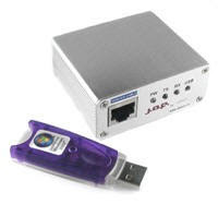
1. Connect your Phone to the box, and start the J.A.F software:
(Double Click on this Symbol on the Desktop)
2. Select the DCT-4 Tab in the J.A.F Software and Press the “Info” Button
After this in the status Box should be a new message like in the picture above
In this Box you can see the:
• Phone Type
• Software Version
• Language Pack of the Firmware
• IMEI
• Product Code
• Ansic Type
• The Provider
• And the unlock codes
3. Now you must select the right Flashfiles. The most Phones need only MCU and PPM, but some need also the CNT package Nokia Communicators need also the APE and ADSP Files. The easiest way to select the right files is to press the
files are selected automatically.
4. If the files are selected Press the “Flash” button now the box is working and after some minutes the Phone will be up to If you want to change the Product code just tick the “Change product code” box also…
NOTE: If you have a dead phone and the “Use INI” Function is also not working click on the “Manual Flash
manual mode. Now the flasher is able to flash the dead phone.
In some cases the Bluetooth chip of the Phone is damaged, so the flasher can’t flash this section and will stop flashing.
If you have such problems click on the “Skip BT” Button to solve the Problem. Now the flasher leaves out the Bluetooth part
How to Unlock a DCT-4 Phone:
1. Connect the Phone to the Box
2. Select “Init Simlock” then Press the “Unlock” Button.
If you want to lock the Phone to only one Network tick the “Lock to Network” Button and enter the Operator Code and then
How to make a “Factory Reset”:
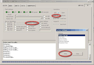
Tick the “Factory Settings” button and then Press the “Service” button. Then a new windows appears there you can select you want. (Factory Set Full is recommend) Wait until the message ”Done!” appear in the “Status and Results”
How to read/write a PM:
1. Connect you phone to the box. And go to the DCT-4 Tab. In the Service Operations you have three possibilities for read, one for writing and erasing. So just check the option you want and press then the “Service” button.
2. If you select “read” the Program will ask you where to start reading the PM. The whole PM is saved from 0 to 255. So enter address field 0.
3. And for the end address tip 255 then press also “OK” button. Now it will take some minutes to read the PM
4. The PM is now saved in C:\Program Files\Nokia\Phoenix\
5. If you want to write a PM just tick “write PM” instead read. But then the Program will ask you if you are know what you are cause in the PM are all important settings for the Phone saved. But just click the “Yes” Button.
6. Now you must be carefully, flash only the write PM into the Phone cause otherwise the Phone won’t work any more. Then 7. Now the Box starts to write the PM to the Phone. Wait until there is the message “Done!” in the status and results box.
NOTE: In the PM are all important settings of the Phone saved. So be carefully with this file. Flash it only if you have a reanimate it.
How to edit the Security Code:
Connect the Phone to the box and select “User Code Edit” and press then the “Service” Button. Then a new window will appear.
If you want to read the current user code Press “Read Code”.
The editing is also very simple. Write the new Security Code into the Box (5 Digit only) and press then press the
How to make a “Format User Area”
This feature is especially for WD2 Phones, like the 7610 or the 6600. After flashing such a WD2 Phone it’s recommend to “Format User Area”. To delete all old User files, which are maybe not compatible with the new Firmware.
Just tick the “Format User Area” Button and then press the “Service” button. Then wait until there is the message
The Product Manager:
This Feature is for reading/writing special Phone information like the Manufacture month or the Hardware Version.
ACD Reading
This is a nice feature for reading some Voltages and some other interesting things.
How to repair Bluetooth problems:
If the Bluetooth function isn’t working after flashing, connect the phone to the box and click the
Then wait till the message “Done!” is in the status and results box. Now the BT of the phone should work
Sunday, November 15, 2009
Nokia DCT- 4 Flashing Manual with JAF
Posted by zuhri at 4:34 AM 0 comments
Nokia DCT- 3 Flashing Manual with JAF

How to install a Wintesla Flashfile:
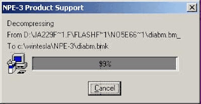
1. Double click on the icon of the Flashfile
2. Then the installation of the Flashfiles starts.
3. Click “Install”, after this the program ask you where to put the files in. The destination
folder should always be: “c:\wintesla”. Then press the “OK” Button.
4. After this the program starts to copy the files (It will take some minutes)
5. After copying the files you should get this Message:
Press the “OK” button. Now the Flashfiles are successfully installed.
How to Flash a DCT-3 Phone:
1. Connect your Phone to the box, and start the J.A.F software:
(Double Click on this Symbol on the Desktop)
2. Select the DCT-3 Tab in the J.A.F Software and Press the “Info” Button
After this in the status Box should be a new message like this one:
In this window you can see the current Firmware of the Phone and the IMEI and the
Security Code. If there is no Security code displayed, is the code 12345.

3. Before you can flash the Phone you must select the right flashfiles. The MCU is the
file where the whole software is saved. The PPM is only the language file. So click
“Flash MCU” then a new Window appear. Select the MCU file of the phone and then
press “Open”
4. After pressing OK a second windows appear for the PPM file. Select the Language
File you like and then press also the “Open” button.
5. Now the files for flashing are selected. Just Press the “Flash” Button to start flashing.
If you want to flash the Phone Manual (recommend for dead Phones) tick the
“Manual Flash” box.
Important: Never disconnect a Phone during the flashing procedure. And wait until
there is the Message: Done!
After this the phone is up to date.
How to Unlock a DCT-3 Phone:
1. Connect the Phone to the Box
2. Select “Init Simlock” then Press the “Unlock” Button.
If you want to lock the Phone to only one Network tick the “Lock to Network” Button and
enter the Operator Code and then press Unlock.
How to make a “Factory Reset”:
Tick the “Factory Settings” button and then Press the “Service” button. Wait until the
message ”Done!” appear in the “Status and Results” Box.
How to flash a virgin EEPROM:
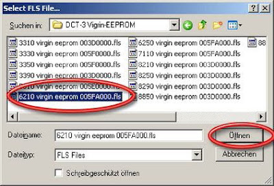
1. Press the “Write FLS” Button, and select your Phone Model and press “Select”
2. Select the EEPROM and press “Open”
3. Then the J.A.F software will ask you for the start address of the EEPROM. Enter the
address and then press “OK”
4. This is a Log of the flash procedure:
BOX OK!
JAF DCT4/BB5 LOADERS DIR: C:\Programme\Nokia\Phoenix\Flash\
JAF USB LOADERS DIR: C:\Programme\Nokia\Phoenix\FlashUSB\
JAF DCT3/DCTL LOADERS DIR: C:\Programme\Nokia\Phoenix\Flash3\
Booting phone...
BOOT file: C:\Programme\Nokia\Phoenix\Flash3\dct3bt2.tia
Boot size is 0x03BC
0x61,0x07
Boot is ready...
Operation took 0 minutes 3 seconds...
Flash ID is 0x96888900
ALIAS ID: 96888900
BOOT file: C:\Programme\Nokia\Phoenix\Flash3\I28F160.TIA
Loader size is 0x17CC; Loader chk: 5fb7
Loader is ready...
Operation took 0 minutes 1 seconds...
Erasing...
Erasing area: 005F0000 - 00600000...
Operation took 0 minutes 1 seconds...
Writing PMM...
Operation took 0 minutes 1 seconds...
Terminate Flash Session...
Now the new EEPROM is uploaded!
NOTE: In the EEPROM file are all setting of the Phone saved. If you have a dead phone
and it is still not working after flashing, upload a new EEPROM, and then it should work
Posted by zuhri at 1:58 AM 0 comments
Thursday, November 12, 2009
How to know Nokia BB5 Engine Structure
A little dated but may be of use to the newcomers...
Single Engine Structure
ENOS = EPOC(Symbian OS) + NOS(Nokia OS)
ENOS based products -> 3650, 6600, 9210 …
EPOC and NOS operate mostly independent
Both operating systems are executed on the same core – they use the same common memory devices and resources
CMT-APE (NOS-EPOC) communication based on Phone protocol
On execution NOS tasks have always higher priority
NOS is mainly focused on cellular modem activities (RF, powers, …)
EPOC is mainly focused on user interface activities
Dual Engine Structure
Dual engine products –> 6630, 9500, 6680 & 6681
Both operating systems are physically separated on different cores – they have own memory devices and resources
CMT-APE (NOS-EPOC) communication based on Phone via physically bus (X-BUS)
NOS is totally focused on cellular modem activities
EPOC is totally focused on user interface activities
Power Up Steps
After Switch On
RETU activates Sleep Clock, VANA, VIO, VR1 and VDRAM
Voltage @ Retu RSTX pin will then enable TAHVO ASIC
TAHVO enable VCORE (RAP3G) and its internal oscillator to drive VCOREA (OMAP)
VCTCXO regulator is set on and RFClk (38.4 MHz) is started by RETU regulator
RETU release PURX after 16 ms after RFClk is stable
2.4 MHz SMPS clock for TAHVO is produced
After PURX is released and 2 rising edge of 2.4 synchronization clock is detected, TAHVO will use it to drive VCOREA
System is up and running
Software is used to switch on other regulators
RAP3G
RAP3G is a 3G Radio Application Processor
Successor for TIKU (used in NOKIA 7600) with some technical improvements and additional features
In general RAP3G consists of three separate parts:
Processor subsystem (PSS) that includes ARM926 MCU as a main processor, Lead3 PH3 DSP and related functions
MCU peripherals
DSP peripherals
RAP3G is running with NOS and takes care of all cellular modem activities
RAP3G core voltage (1.40V) is generated from TAHVO VCORE and I/O voltage (1.8V) is from RETU VIO. Core voltage in sleep mode is lowered to 1.05V
RETU
RETU is the primary EM ASIC including following functional blocks:
Start up logic and reset control
Charger detection
Battery voltage monitoring
32.768kHz clock with external crystal
Real time clock with external backup battery
SIM card interface
Stereo audio codecs and amplifiers
A/D converter
Regulators
Vibra interface
Digital interface (CBUS)
RETU ASIC does not include security functions such as UEM(E,K)
TAHVO
TAHVO is the secondary EM ASIC including following functional blocks:
Core supply generation (VCORE & VCOREA)
Charge control circuitry
Level shifter and regulator for USB/FBUS
Current gauge for battery current measuring
External LED driver control interface
Digital interface (CBUS)
TAHVO ASIC does not include security functions such as UEM(E,K)
OMAP 1710
OMAP is the application processor running with Symbian operating system (EPOC)
Platform for executing all user related application. Main interfaces:
Camera interface
Display interface
Bluetooth interface
MMC interface
USB interface
Keyboard interface
X-Bus for communication with RAP3G
OMAP is a standard ASIC designed by Texas Instruments and used also by other manufacturers of mobile phones and handheld PCs
Core voltage VCORE=1.4V is generated by discrete SMPS, and is lowered to 1.09V in sleep mode
I/O voltage VIO=1.8V is generated by RETU
CMT Flash
CMT Flash memory is used to store:
MCU program code
DSP program code
Tuning values
Certificates
Capacity: 64Mbit
Logic and supply voltage for NOR Flash is supplied from VIO (1.8V)
Flash clock is 48MHz (192MHz/4)
CMT SDRAM
CMT SDRAM is mainly used as a dynamic data storage for MCU data
Capacity: 64MBit
SDRAM core voltage (1.8V) is generated by RETU’s VDRAM regulator
I/O voltage (1.8V) is generated by RETU’s VIO regulator
SDRAM clock is 96MHz (192MHz/2)
APE Combo Memory
APE Flash is used to store application code and user data
It is not possible to execute code directly from Flash -> executables need first to be loaded to DDR and run from there
Capacity: 256Mbit (Flash), 256Mbit (DDR)
Core voltage for DDR is VDRAM 1.8V
VIO 1.8V is for DDR I/O voltage
Both NAND core and I/O voltages are generated by RETU
DDR clock is 110MHz (220MHz/2)
Flash interface speed is 22MHz
Front Camera
The front camera is controlled and its data is collected by OMAP
The I/O voltage of OMAP is 1.8V, and the one of the camera is 2.8V; therefore a level shifter is needed
The camera is powered with two different voltages from LDO (Low-dropout voltage) regulators:
VCAM 1.5V for camera digital circuits, and sensor A/D-converter
VCAM2 2.8V for camera I/O, and sensor photo diode
Back Camera
Connected to OMAP via data and control interfaces
Data transfer: through differential serial interface using clock and data
Camera control: bidirectional control interface compatible with I2C standard using SCL&SDA signals (1.8V)
Camera digital voltage is VCAM (1.5V) from discrete LDO
Camera ****og voltage is VAUX (2.5V) from RETU
Additional control signals
Vctrl: high (1.8V)=camera active low (0V)=camera inactive
ExtCLK: clock from OMAP1710 (9.6MHz)
Camera Flash Light
Designed to give more light when taking pictures in dark environment
The same LED is also used as an indicator light for indicating when:
a video clip is being recorded
a picture is taken
TK1189 is the SMPS for FLED. The enable of TK1189 is controlled by two hosts:
flash mode is controlled by the camera
indicator mode is controlled by OMAP
Bluetooth
Single chip BT BC3 (includes RF, BB & ROM memory)
UART interface for control/data with OMAP
PCM interface for audio data with RAP3G
IO voltage 1.8V from VIO
Reg voltage 2.8V from VFLASH1
Clock 38.4MHz from RF part
Ambient Light Sensor
Ambient Light Sensor is located in the upper part of the phone and consists of:
Light guide (part of front cover)
phototransistor + resistor
NTC + resistors
RETU
Information of ambient lighting is used to control backlights of the phone:
Keypad lighting is only switched on when environment is dark/dim
Display backlights are dimmed, when environment is dark/dim
Memory Card Interface
Reduced size MMC can be used to store photos, videos, etc…
MMC is connected to OMAP
Interface voltage level is 1.8V and power supply from RETU VSIM2
EMC protection by using ASIPs (Application Specific Integrated Passive)
MMC is powered down when MMC cover is opened
Cover lid open = signal connected to GND
Cover lid closed = signal connected to 1.8V
Posted by zuhri at 5:08 AM 0 comments


